This article originally featured on Defencyclopedia and is republished with permission. It may be read in its original form here.
SUMMARY
The best position for a sensor on a ship, is on top of the highest mast. Multiple sensors mean multiple antennas; hence ending up close together. Such an arrangement requires the need to switch one system off before another one can be used. As all sensor systems are installed separately on the ship, and then subsequently integrated and tested, they add considerably to the time and cost required for building a naval vessel.With recent development of integrated masts for warships, gone are the dozens of antennas and sensors found on practically every flat topside surface of a modern naval vessel.
These integrated masts allow the exploitation of modern materials and technology to improve sensor performance and coverage with pre-outfitting, leading to reduced cost of construction due to reduced time overruns. This article, by Commander Nitin Agarwala, who is now a contributing author for Defencyclopedia, explores the developments in integrated mast design for integration of electronic warfare (EW),communication and Radar and their future in warship construction.
INTRODUCTION
How does an antenna become designated for use in navigation, weapon fire control, communications, electronic countermeasures or for any other reason, and ultimately installed on board a Naval surface ship? The answer should be, it’s part of the antenna design procedure. Though the answer is simple, the process is not. There was a time, when this design procedure, referred to as dart-boarding, was based on an educated guess for the most feasible layout of the antennas, followed by experimental verification.
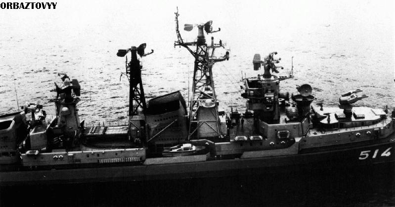 The multiple mast and cluttered antenna layout on a 1970’s era Soviet Kashin class destroyer
As the reliance on electronic systems such as communications, radar,navigation, gunfire control, friend-or-foe identification, electronic countermeasures, and aircraft operations increased, one realized that complex, intricate below-decks electronic equipment was virtually useless unless matched with satisfactory antenna performance. Hence former methods of antenna design and topside arrangements were no longer adequate and dart-boarding disappeared – to be replaced by careful scientific planning. These electronic systems divided the shipboard antennas into three broad groups.
- Omni-directional antennas – used mainly for communications, air navigation, and passive reception. These satisfy the need of ships and aircraft to maneuver independently of each other and fixed radio stations.
- Directional antennas – used for transmitting and receiving spatially concentrated energy in one direction at a time. These are used for radar, gunfire control, and satellite communication to obtain information about or from remote objects.
- Directional antennas – used to determine bearing of incident radiation; and is used primarily for direction finding navigation and Electronic Countermeasures (ECM).
For an operational naval platform, the basic minimum required sensors are communication antennas from HF to UHF, navigation radar, surveillance radar, IFF, Fire Control Radar, ESM, jammers, electro-optical sensor systems and missile up-links.Providing these large number and variety of distinct services on the antenna in the extremely restricted space presents many very-difficult and different problems which do not arise in other technical disciplines.
Clustering of so many antennas in so little space,plus the necessity for simultaneous emission and reception together with the undesirable, but unavoidable, electromagnetic coupling to, and re-radiation from, a host of other shipboard metal objects, results in a most trying system integration problem for the ship. Strenuous efforts must be made to reach a compromise with all competing topside subsystems so as to provide the least degradation in overall performance.
TYPES OF MASTS
To meet the requirement of these sensors, the Naval Architects have hence used
- Pole masts
- Tripod masts
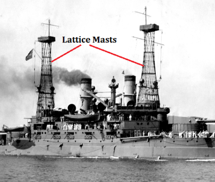
- Lattice masts
- MACK (Mast-Stack) masts
- Enclosed masts
- Solid masts


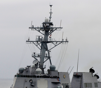
 Enclosed mast
The various types of masts have been a result of changing requirement of the navies and the developing technology used over the years. Of all these masts, a plated mast, even with a higher weight than a lattice mast, is preferred in most cases due to its advantages of lower radar cross-section, improved through life maintenance (due to enclosed structure), lesser vibration and ability to handle larger weight of modern equipment.

The design of the mast however is not limited to just the placement of thesensors.The mast design has a direct bearing on the design of the vessel itself as its weight will impact the stability performance, air resistance will impact the ships speed and the arrangement of the antennae will affect the top side electromagnetic environment and RADHAZ (radiation hazard).
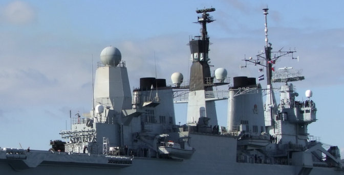
When designing, one needs to structurally integrate the mast to the ship to ensure strength due to both static and dynamic loads (whipping loads due to hull slamming, air resistance, shock), provide access, power and cooling air and study the effect of the heat plume from the exhausts/funnel impinging on the antennae. The picture of HMAS Perth shows the effect of proximity of the smokestack to the masts on the ship.
NEXT GENERATION MASTS
Conventional warship masts are plagued with a variety of downsides which include large amounts of steel making the ship topside heavy resulting into weight penalty, expensive maintenance due to exposed sensors, wooding as a result of sensor / mast interactions, electromagnetic induction due to spurious reflections and poor screening and impingement in return causing a high radar signature. This has led to designers looking at alternatives.
Accordingly in recent years, there has been a significant interest in the concept of composite masts, with a variety of designs being developed. These designs aim to house sensors and antenna within the protection of the mast and use frequency sensitive shielding to allow the sensors to “see” through the mast panel structure thus offering an improved signature and arc of coverage. Such major initiatives are:
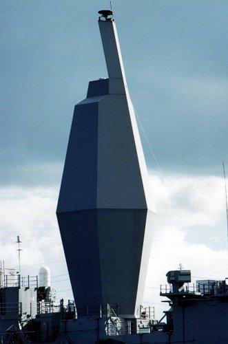 A photo of the enclosed hexagonal mast on the USS Radford
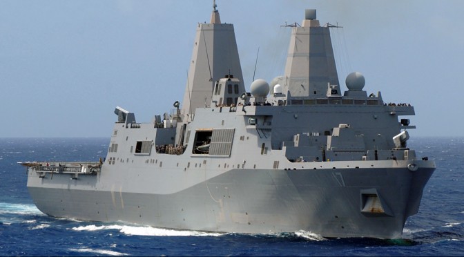
- The Advanced Enclosed Mast/Sensor (AEM/S) system designed by the US and initiated in 1995 is a hexagonal (used onboard USS Radford DD-968) or an octagonal (used onboard U.S.S. San AntonioLPD-17) structure. It encloses the existing radar and other sensitive equipment,protecting them from the environment thereby reducing maintenance requirements. The lower half of the AEM/S system serves to hold up the top half. The case of the lower half is balsa. An electromagnetic (EM) shield compartment that uses reflecting metallic shielding is included in a portion of the lower half of the mast to meet design requirements. The top half contains a tailored sandwich composite material made up of a foam core, with frequency selective material, as well as structural laminate skins.
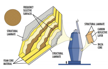
 Octagonal Advanced Enclosed Mast/Sensor on USS San Antonio
- The Advanced Technology Mast (ATM) designed by the UK, comprises of a steel substructure clad in advanced fibre reinforced plastic (FRP) composite panels,which incorporate radar-absorbing layers. Sensors are installed in interchangeable modules mounted within the cladding. The philosophy of the mast is intended to support future surface warship designs and retrofit to existing ships. The sensors and radio equipment are completely enclosed in the radar reflective mast structures. The masts look like unstayed pole masts with very large rectangular cross-sections, tapering from the base to the top.
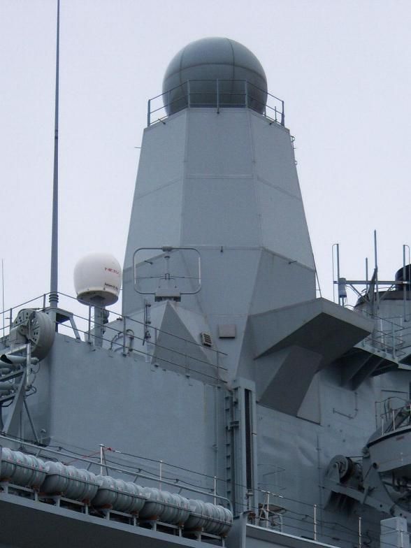 A close-up of the Advanced Technology Mast
The Integrated mast (I-MAST) designed by Netherlands, is a completely different design approach from the traditional sensor layout. This mast type integrates the sensors into the structure itself. One central mast structure houses the radar, optronic, and communication sensors and antennas as well as all cabinets and peripherals. The Integrated Mast concept improves the undesirable situation of having to equip a ship with sensors and antenna after she has been completed in full. In the I-Mast, the mast and the equipment are built and tested while the ship is under construction. When the ship is ready, the mast is put on the ship as a turnkey system. It has a comparatively simple interface to the ship’s power supply, cooling water supply, combat system, and mechanical deck structure, making installation a plug and play operation.
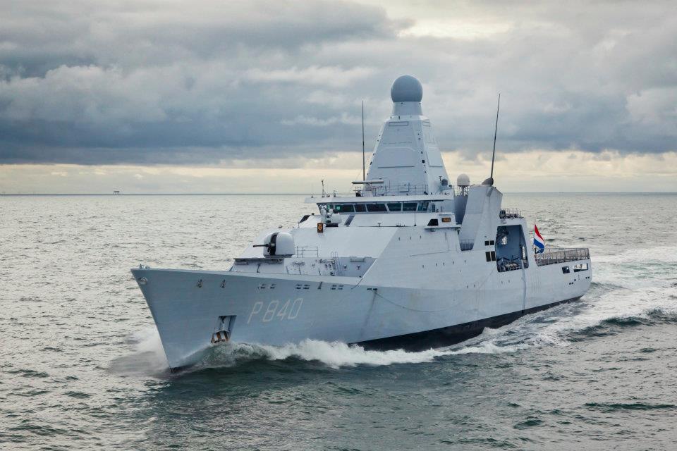
The mast itself is a fully air tight module forming part of the ship’s citadel, providing environmental protection against shock, blast, vibration, solar radiation,temperature, uptake efflux, electromagnetic radiation and chemical, biological, radiological or nuclear weapons. An external load-bearing steel structure has been adopted to facilitate the integration of different types of sensors and communications, with equipment arranged over four deck levels (a top deck,upper antenna deck, lower antenna deck and an equipment deck. A shielded duct or “backbone” routes cabling and cooling circuitry up through the centre of the mast to serve individual equipment.
All processing cabinets are sited on the equipment deck. This is also the floor of the mast module and the interface to the ship platform through a single crew entry hatch and two cable entry panels fitted port and starboard. Services routed through these panels comprise water, air, own-ship data, power supplies, monitoring and control, dual communication, video and combat system buses, and auxiliary interfaces
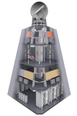 A cut-out shows the sensor layout in the i-Mast
 An illustration showing the various types of sensors present on the i-Mast 500
SENSORS OF I-MAST
All radars and antennas in an I-Mast not only have a full 360° field of view; they are also developed so as to operate simultaneously without interfering each other.Theseradars are non-rotating, four-faced active phased array radars, which in itself is a major performance enhancement. As the four faces operate simultaneously, the radars achieve four times the time on target achieved by a rotating radar. The surface surveillance radar (Seastar) was developed especially for this purpose and it is capable of detecting and tracking small objects (e.g. divers’ head) between the waves,contributing enormously to situational awareness in littoral environments. The details of the sensors as fitted in an I-Mast are as under:
- SeaMaster 400 (also called SMILE) is a non-rotating S-band radar with four faces for air and surface surveillance. It is derived from the proven SMART and APAR radar systems. SM400’s unique concept of multi-beam volume search with four active scanning faces ensures the simultaneous performance of all operational tasks at a high update rate and very low false alarm rate. SM400 also provides helicopter direction and approach capabilities and has three fire control channels. The system’s high number of parallel transmit and receive channels provide a high degree of redundancy.
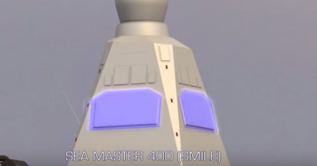 Seamaster S-band radar
- Seawatcher (also called SEASTAR) is a four face non-rotating active phased array X-band radar for naval surface surveillance. The high resolution system automatically detects and tracks asymmetric threats and very small objects such as mines, periscopes. Seawatcher can also be used for helicopter guidance.
 Seawatcher X-band radar
- Gatekeeper is a 360° panoramic electro-optical surveillance and alerter system based on IR/TV technology. Designed to counter emerging asymmetric threats down to small boats and swimmers, Gatekeeper increases short-range situational awareness in littoral environments.
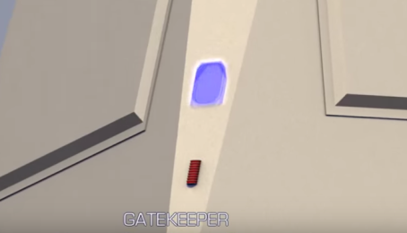 Gatekeeper
 SATCOM antenna dome
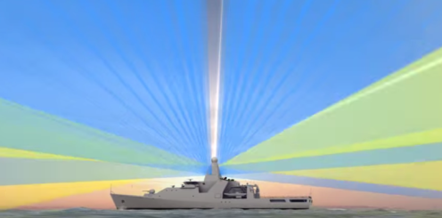 A CGI shows the sensors of the I-mast operating together without any blockage of signals
 - The Integrated Communication Antenna System (ICAS) facilitates the use of standard VHF / UHF communications equipment, is fitted with Link 16 integration, provides excellent transmit/receive isolation, offers estate for auxiliary antennas such as GSM/GPS and is designed for future growth.
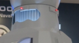 Cylindrical IFF array
- The non-rotating Identification Friend or Foe (NR IFF) uses a cylindrical array fitted to the top of the structure. It is designed to operate with standard interrogator/transponder systems. It is optimized for operation with a non-rotating primary radar.
NEED FOR AN INTEGRATED MAST
Littoral environments are extremely complex given the high density of natural and man-made clutter, crowded commercial air and sea lanes, vehicle traffic along the coastline, and the effects of anomalous propagation on sensor performance. To further complicate the problem, recent years have seen the emergence of an increasingly“asymmetric” threat set (unmanned air vehicles, fast inshore attack craft, gliders, dinghies, swimmers and mines) that are intrinsically difficult to detect in high clutter backgrounds. To resolve such issues the concept of an integrated mast incorporating the principal surveillance sensors and communication systems has evolved.
By resolving the electromagnetic conflicts and line-of-sight obstructions inherent to traditional topside antenna arrangements, the integrated mast aims at delivering an unobstructed field of view, reduced cross section; ease of electromagnetic friction and to simplify shipboard integration. This in return provides a significant benefit in terms of improved operational performance and availability, shorter shipbuilding time, reduced maintenance requirements and significant savings in below-deck volume.
In an integrated mast various antennae are integrated within the design of the mast itself along with the electronic equipment to be “integrated” in the mast as a single unit. The result is a mast which is a structurally self-supporting module. The integrated mast with its technology of integrated sensor concept delivers huge advantages which are:
- Better operational performance
- Higher operational availability due to maintenance possible in the protected, sheltered environment of the Mast, meaning that it is no longer necessary to wait for repairs until weather conditions are safe enough
- Reduced ship-building time
- Reduced maintenance requirements due to non-rotating radars
- Enormous savings in below-deck space
- Reduced signature / increased arc of coverage
- Reduced costs (i) Lower sensor costs due to improved environment(ii) Cheaper maintenance due to lack of corrosion, no re-painting and modular approach
- Reduced topside weight / improved stability
- Reduced EMI – RAM covered decks
- Potential for quick role changes – flexibility, upgradeability
CONCLUSION
Various advanced Mast designs have been produced in the recent past which have been discussed in this paper. All of them have been tested for their structural performance against both environmental and shock loads. One can say with confidence that today the concept of “integrated mast” has become a reality from just a technology demonstration project. Though it is definitely a product which shall become an integral part of the future ship design, however many issues such as the impact of the integrated mast on ship design need to be studied in detail.
One needs to also study issues such as material selection for the mast, access arrangements and structural integration and stability as key aspects among many. Finally the integrated mast designers themselves will continue to be challenged by how to design a mast or series of masts that offer a solution that is sufficiently flexible for fit to a variety of vessel sizes and satisfy differing customer requirements.
Edited by N.R.P
ABOUT THE AUTHOR
Commander (Dr) Nitin Agarwala, a serving Indian Naval Officer commissioned in 1993, is a Naval Architect from Cochin University of Science and Technology and an alumnus of Indian Institute of Technology, Delhi and Kharagpur. The officer has experienced the various facets of a warship as a user, inspector and a maintainer. He is now a part of the design team of naval warships. He has published over 26 papers in various conferences, and journals of national and international repute. His areas of interest are Wave structure interaction problems, Acoustic structure interaction problems, Hydroelasticity related ship structure problems, Corrosion problems associated with ships.

